What's Printed on the Board Is Not What's Inside It

Here's a scenario that probably sounds familiar. You order a pack of five buck converter modules off a well-known marketplace. The listing says 3A output, the silkscreen on the board says 3A output, and you build your project around that number. Then somewhere around 1.8 amps, things start getting warm. At 2.2 amps, the magic smoke escapes. You're left staring at a dead board wondering what went wrong.
What went wrong is that you trusted the printing.
Silkscreen text — the white (or sometimes yellow) labels printed directly onto a PCB — is supposed to tell you something useful. Max voltage, max current, input range, output options. For reputable manufacturers, it usually does. But in the world of ultra-cheap modules churned out in massive batches with minimal QC, that text is sometimes more aspirational than accurate. We decided to stop guessing and start measuring.
What We Actually Tested
We grabbed a cross-section of the kinds of boards that show up constantly in DIY builds: a few common buck converter modules in the XL4016 and MP2307 families, a couple of TP4056-based LiPo charger boards, and a handful of generic 5V linear regulator breakouts. All sourced from the usual suspects — value packs from Amazon and AliExpress, the kind of stuff makers buy in bulk because individually they cost less than a pack of gum.
For each board, we noted what the silkscreen claimed, then we did three things: visually identified the actual components, looked up their real-world datasheets, and ran load tests to find the practical ceiling. The gap between claimed and confirmed was eye-opening.
The Buck Converter Problem
One of the most common offenders is the XL4016-based buck module. These boards frequently carry a "8A max" silkscreen label. The XL4016 chip itself does have an 8A peak rating in its datasheet — but that's a peak, not a sustained output, and it assumes ideal thermal conditions with proper heatsinking.
The modules we tested had no heatsink, a tiny inductor that saturated well below 4A, and trace widths that would make an electrical engineer wince. In practice, sustained output above 2.5A caused the inductor to run hot enough to be uncomfortable to touch, and one module's output voltage started sagging noticeably at 3A. Sustained 8A? Not even close.
The MP2307-based mini buck modules are even more egregious. These little boards — often labeled "3A" — use a chip that the manufacturer's own datasheet rates at 3A absolute maximum under ideal conditions. Real-world continuous current on these boards tops out around 1.2A before thermal throttling becomes a real concern. We measured output ripple climbing sharply above that point, which is the kind of noise that makes microcontrollers do weird things.
LiPo Charger Boards and the Charge Rate Fiction
TP4056-based charger boards are everywhere, and they're genuinely useful little things. Most of them are sold as "1A" chargers. The TP4056 chip is capable of 1A charge current — but only if you install the correct programming resistor. That resistor, labeled RPROG on the datasheet, sets the charge rate.
On a surprising number of boards we measured, the installed resistor wasn't the 1.2kΩ value that sets 1A charging. Several boards had 2kΩ resistors installed, which limits charging to around 580mA. One board had what appeared to be a 3kΩ resistor, which would cap charging at roughly 400mA. These boards will still charge your battery — just slower than advertised, which means your project's recharge time estimates are wrong before you even write a line of code.
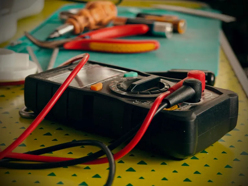
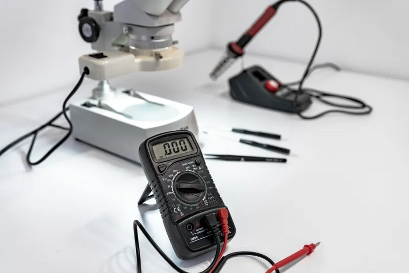
This one is easy to check yourself. Pull out a decent multimeter, measure the resistor in the PROG position, and cross-reference it with the TP4056 datasheet. Five minutes of verification can save hours of debugging.
Linear Regulator Breakouts: Voltage and Current Surprises
Generic 5V regulator breakout boards — the kind built around the classic 7805 or its cousins — showed a different flavor of silkscreen dishonesty. Several boards we tested were labeled with input voltage ranges that exceeded what the actual component could safely handle.
One board claimed an input range up to 35V. The chip soldered to it was marked in a way that suggested it was a standard 7805, which has an absolute maximum input of 35V in the datasheet — but with a 5V output, that's a 30V dropout across the regulator. At any real current draw, that becomes a heat problem almost immediately. There was no heatsink provision on the board, and the thermal pad wasn't connected to any copper pour. Running this thing at 24V input and 500mA output turned it into a hand warmer within about 90 seconds.
Other boards had the opposite problem: components that looked like 7805s but measured output voltages that wandered between 4.85V and 5.15V depending on load. Fine for some applications, potentially problematic for anything with tight voltage tolerances.
Why This Keeps Happening
The cynical answer is that nobody's checking. When you're producing boards in batches of 10,000 and selling them for $0.40 each, there's no margin for rigorous QC. The silkscreen gets designed once based on the intended BOM, and then the actual assembly process uses whatever components are available and cost-effective on a given production run. The printing doesn't change. The components do.
Some of this is also legitimate spec interpretation pushed to its absolute limit. A chip that can theoretically handle 8A for 10 milliseconds in a 25°C lab becomes an "8A module" in the listing. It's not technically a lie — it's just a number stripped of every relevant context.
How to Protect Yourself
The good news is that verification isn't hard, it just takes a few extra minutes before you commit to a design.
Read the IC markings, not the board labels. The chip itself usually has a part number. Look it up. The actual datasheet tells you real limits under real conditions.
Derate aggressively. Whatever the stated max is, plan your design around 60-70% of that number at most. Budget components running near their rated limits tend to fail in ways that cascade.
Measure before you build. A cheap multimeter and a resistive load (even just a few power resistors) can tell you a lot about what a board actually does versus what it claims. Spend 10 minutes bench-testing a module before you embed it in a project.
Check the programming resistors. On configurable boards like TP4056 chargers or adjustable buck converters, verify that the passive components actually match the configuration the board claims. This takes 30 seconds with a meter.
Buy from sellers who post photos of the actual board. Listings that show real component photos rather than renders are more likely to be accurate. It's not a guarantee, but it's a filter.
The Bottom Line
Budget components are still a fantastic deal for most maker applications. We're not here to tell you to stop buying cheap boards — that would be a weird message from a site called Cheap5V. But there's a difference between buying affordable parts with realistic expectations and buying parts based on silkscreen specs that were optimistic to begin with and may not even match what's installed.
Trust the datasheet. Verify the passives. Derate the ratings. And maybe keep a fire extinguisher nearby the first time you push a new module to its supposed limits.