5V and 3.3V on the Same Breadboard: A Recipe for Fried Pins and Dead Projects
You've triple-checked your wiring. You've re-uploaded the sketch six times. Your ESP8266 is acting like it's possessed, your sensor readings are garbage, and your Arduino Uno sits there looking innocent. Everything should work. The schematic says so. The YouTube tutorial says so.
But nothing works.
Here's a frustrating truth that doesn't get nearly enough airtime in beginner tutorials: a huge percentage of mysterious IoT project failures aren't software bugs or bad solder joints — they're voltage mismatches. Specifically, the slow-motion collision between 5V logic and 3.3V logic sharing the same breadboard, the same signal lines, and sometimes even the same power rail.
Let's talk about why this happens, what it actually destroys, and how to fix it on a shoestring budget.
The Two-Voltage World We Now Live In
For a long time, 5V was king. Arduino Uno, classic AVR chips, older sensors — everything ran at 5V, and life was simple. Then the microcontroller world started shrinking, both physically and in terms of operating voltage. Modern WiFi modules, Bluetooth chips, and basically every ESP-family board runs at 3.3V. So does most of the cheap sensor ecosystem that's flooded the market over the last decade — I2C temperature sensors, OLED displays, IMUs, GPS modules, you name it.
The problem? A lot of makers are still pairing these newer 3.3V devices with 5V Arduinos because that's what they have in the parts drawer. And that combination, handled carelessly, is a recipe for intermittent failures at best and permanently damaged hardware at worst.
What Actually Breaks — and Why
Let's get concrete. When a 5V Arduino sends a HIGH signal on a digital pin, it pushes out approximately 5 volts. That signal travels down your jumper wire and lands on the input pin of your 3.3V ESP8266, your cheap I2C sensor, or your GPS breakout board.
Most 3.3V devices have an absolute maximum input voltage of 3.6V — sometimes even lower. Feed them 5V and you're not just out of spec, you're potentially cooking the internal protection diodes or the input stage of the chip itself. It might not die immediately. That's the cruel part. It might just start behaving erratically — giving you wrong readings, locking up randomly, or failing to respond to commands. You'll spend hours debugging software that isn't the problem.
The reverse scenario is subtler but also real. When a 3.3V device tries to signal HIGH back to a 5V Arduino, it outputs around 3.3V. The Arduino's digital input threshold for HIGH is typically around 3V, so this usually works — but it's marginal, especially at higher speeds or with longer wire runs where signal integrity degrades. Some 5V chips are more tolerant than others. Some aren't. You're gambling.
The Failure Modes Nobody Warns You About
Scenario 1: The Zombie Sensor Your sensor powers up, responds to initial queries, then starts returning nonsense data or stops responding entirely after a few minutes. Classic sign of input overvoltage stress. The chip isn't dead yet, but it's not happy.
Scenario 2: The Flaky WiFi Module Your ESP8266 connects to WiFi fine, then drops out randomly. You blame the router, the library, the moon. But if its UART RX pin is being driven by a 5V Arduino TX line, you may be slowly degrading the input protection on every single transaction.
Scenario 3: The I2C Bus That Won't Talk You're pulling the SDA and SCL lines high through pull-up resistors to 5V, and your 3.3V sensor is on the same bus. The bus voltage is now 5V. Your sensor's datasheet says max 3.6V on those pins. This is one of the most common silent killers in cheap maker builds.
The Fix: Logic Level Shifting Without Breaking the Bank
Here's the good news — this is a completely solvable problem, and the solutions cost almost nothing.
Option 1: The Bidirectional Logic Level Shifter Module
These little breakout boards — usually built around the BSS138 MOSFET — cost between $0.50 and $2 depending on where you buy them. They handle bidirectional shifting for I2C and UART lines, support multiple channels (typically 4 or 8 per board), and require almost no external components. You connect your 5V rail to the HV side, your 3.3V rail to the LV side, and run your signal lines through the middle. Done.
For I2C specifically, make sure you're using a shifter rated for I2C (the BSS138-based ones work well). Some cheap unidirectional shifters on the market will corrupt your I2C bus. Read the listing carefully — or just buy the BSS138 type and move on.
Option 2: The Voltage Divider (For One-Way Signals)
If you only need to shift a signal in one direction — from 5V down to 3.3V — a simple resistor voltage divider works fine for low-speed signals. Two resistors, maybe 10 minutes of work. A 1kΩ and 2kΩ resistor in series from your 5V signal to ground, with the output taken from the middle junction, gives you approximately 3.33V. That's well within spec for any 3.3V input.
This won't work for high-speed signals like SPI at several MHz, and it's definitely not bidirectional. But for something like a button press or a slow UART line? It's perfectly adequate and costs pennies.
Option 3: Just Run Everything at 3.3V
Sometimes the cleanest solution is to stop fighting the voltage mismatch entirely. If your project is ESP32 or ESP8266 based, those boards have 3.3V GPIO. Buy sensors that run at 3.3V (most modern ones do). Ditch the 5V Arduino entirely for that project. One power rail, no level shifting, no headaches.
The catch is that some sensors and actuators genuinely need 5V — certain servo controllers, older LCD displays, relay modules. In those cases, you still need the shifter. But for pure sensor-and-WiFi builds, going all-in on 3.3V is often the path of least resistance.
Quick Reference: Which Cheap Parts Play Nice Together
| Component | Voltage | 5V Tolerant Inputs? |
|---|---|---|
| Arduino Uno (ATmega328P) | 5V logic | Yes (it outputs 5V) |
| ESP8266 (NodeMCU, Wemos D1) | 3.3V | No |
| ESP32 | 3.3V | Some pins, not all |
| Cheap I2C OLED (SSD1306) | 3.3V or 5V | Varies by board — check |
| DHT11 / DHT22 | 3.3V–5V | Generally yes |
| Generic I2C sensors (BME280, etc.) | 3.3V | No |
| Classic 16x2 LCD (no I2C backpack) | 5V | Yes |
| HC-05 Bluetooth | 3.3V | No |
When in doubt, look up the absolute maximum ratings in the component's datasheet. That number — not the operating voltage — is what tells you how much abuse the input pins can actually survive.
The Bottom Line
The 5V-to-3.3V transition in the maker ecosystem happened gradually, and a lot of tutorials, kits, and YouTube videos haven't caught up. The result is a generation of breadboard builds quietly destroying their own components while the builder blames everything else.
The fix is cheap. A handful of level shifter modules costs less than a fast food lunch. A bag of resistors costs even less. Understanding the problem is free.
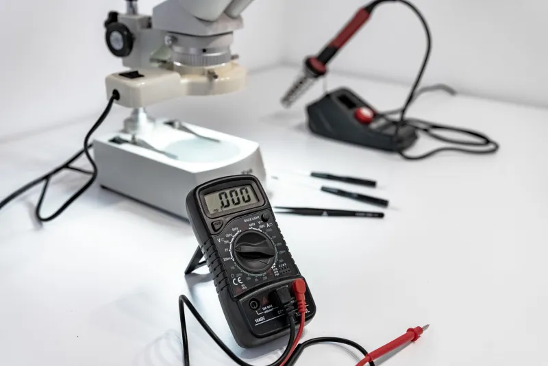
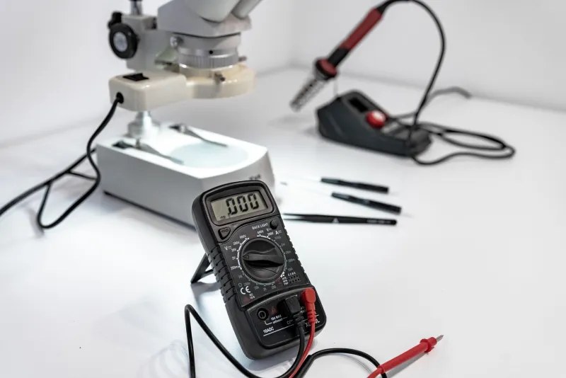
Next time your IoT project goes sideways, before you reflash the firmware or buy replacement parts, grab a multimeter and actually measure what's on your signal lines. You might be surprised — and relieved — by what you find.