Every Cheap Adapter You Stack Makes the Next One Worse — Here's the Math
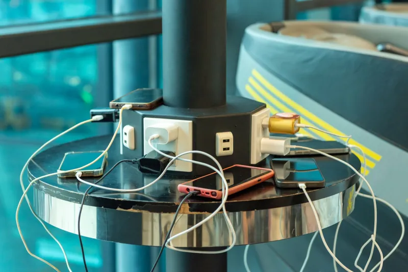
You've been there. The project is almost done. You've got a Raspberry Pi running, an Arduino on a breadboard, a couple of sensors, maybe a small OLED display. Everything works fine in isolation. Then you plug one more thing into the power strip — a USB hub, another wall wart, a second buck converter — and suddenly the Pi is crashing, the Arduino is behaving strangely, and the sensor readings are garbage.
Nothing obviously broke. You didn't blow a fuse. You didn't see smoke. But something is clearly wrong.
Welcome to the 5V trap. It's not a single point of failure. It's a compounding chain of small failures that only shows up when everything is running together.
Why Budget Components Are Designed for Isolation, Not Stacking
Here's something the spec sheet on your $4 wall adapter will never tell you: that adapter was characterized at a single load, in a controlled environment, feeding a single device. Nobody at the factory hooked it up to a USB hub that feeds three more regulators that each power their own microcontrollers.
Cheap wall adapters — the kind that flood Amazon and show up in every maker's junk drawer — typically use unregulated or loosely regulated designs. At light load, they often push above their rated voltage. At full load, they sag below it. The window in between is where they're "happy," and it's narrower than you'd think.
When you chain another component downstream — say, a cheap USB hub with its own internal voltage drop — that hub is now working with whatever the wall adapter happens to be outputting at that moment. If the adapter is already sagging to 4.7V under partial load, the hub drops another 0.2–0.3V in its internal wiring and protection circuitry. Now the device at the end of the chain is seeing 4.4V. That's below the operating floor for a lot of microcontrollers and single-board computers.
We Built the Stack and Measured It
To put real numbers on this, we built a representative "maker power chain" using components that are genuinely common in US hobbyist setups:
- A generic 5V/2A wall adapter (no-name, bought in a 6-pack)
- A 4-port USB hub rated at 5V/2.4A total
- A cheap AMS1117-based 3.3V LDO regulator module
- A small buck converter module rated at 5V output
We measured voltage at each stage using a bench multimeter, then added load incrementally using a dummy load resistor bank.
At 25% load (roughly 500mA total): The wall adapter was outputting 5.18V — a little high, but fine. The USB hub delivered 5.01V at its ports. The LDO module output 3.28V. The buck converter held 4.97V. Everything looked reasonable.
At 75% load (roughly 1.5A total): The wall adapter dropped to 4.81V. The hub was now delivering 4.62V. The LDO — which needs at least 4.75V input to maintain 3.3V output — was outputting 3.11V and getting warm. The buck converter, being a switching regulator, held up better at 4.94V, but only because it was drawing less current at this point.
At 95% load (pushing close to rated maximums): The wall adapter sagged to 4.58V. The hub output was 4.39V. The LDO had given up on regulation entirely and was outputting 3.08V while its surface temperature hit 71°C — hot enough to be uncomfortable to touch. The buck converter was still holding 4.89V, but the input voltage was now low enough that efficiency had cratered and it was generating noticeably more heat than before.
None of these components failed outright. But every device downstream would have been operating outside its reliable voltage window. That's your "random" crashing, your corrupted sensor data, your inexplicable I2C errors.
Thermal Stacking Is the Part Nobody Talks About
Voltage sag is the obvious problem, but heat is the sneaky one.
Cheap linear regulators like the AMS1117 dissipate the voltage difference between input and output as heat. When the input voltage rises (like when your wall adapter is lightly loaded), the regulator has to burn off more power as heat. When multiple regulators are packed into a project enclosure or sitting on a crowded breadboard, they heat each other up.
Heat degrades performance. A warm LDO has higher dropout voltage, meaning it needs even more headroom to maintain regulation. A warm wall adapter has higher internal resistance, meaning it sags harder under load. These effects compound each other in a feedback loop that tightens as your project grows.
We saw this clearly when we enclosed our test stack in a small project box for 20 minutes. The same load that produced 4.62V at the hub output in open air was producing 4.51V in the enclosure. The LDO surface temperature jumped from 71°C to 88°C. That's getting close to the thermal shutdown threshold on some cheaper modules.
The Fixes Are Cheap — If You Know What to Do
None of this means you can't build complex, multi-device projects on a budget. It means you have to think about the power chain as a system, not a collection of independent parts.
Upsize your source. If your project draws 1.5A at peak, don't use a 2A adapter. Use a 3A or 4A adapter. Budget adapters are typically rated at their absolute maximum, not their comfortable operating range. Give yourself real headroom.
Cut the hub out of the power chain. USB hubs are great for data. They're terrible as power distributors in maker projects. Power your devices directly from the wall adapter or your bench supply whenever possible. Use the hub for USB communication only, not as a power rail.
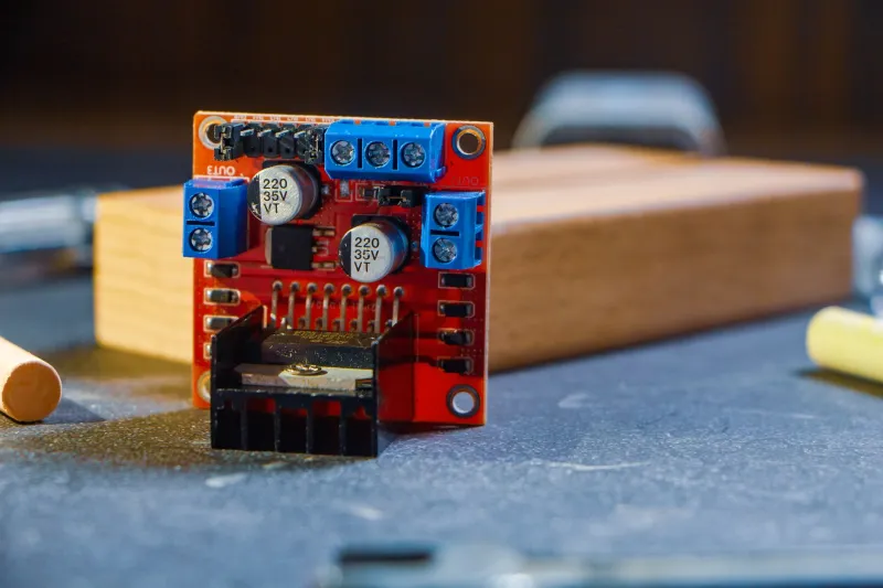
Replace LDOs with buck converters where you can. A switching buck converter from 5V to 3.3V is more efficient, runs cooler, and handles input voltage variation much better than an LDO. The cheap XL4005 or MP2307 modules available for under $2 each will outperform an AMS1117 board in almost every real-world stacking scenario.
Add bulk capacitance at each stage. A 470µF or 1000µF electrolytic cap across the power rails at each major stage smooths out transient voltage drops and gives regulators a moment to recover during current spikes. This is one of the cheapest and most effective things you can do to stabilize a multi-device project.
Measure before you trust. A $12 multimeter and five minutes of voltage checks at each stage of your power chain will tell you more about what's actually happening than any spec sheet. If you're seeing anything below 4.75V at a 5V rail feeding a microcontroller, you have a problem — even if everything seems to be working.
The Stack Always Costs You Something
Every component you add to a power chain introduces resistance, voltage drop, and heat. Budget components do this more than quality ones, and they do it less predictably. That doesn't make them useless — it makes them something you have to design around.
The makers who get burned by the 5V trap aren't doing anything wrong, exactly. They're just treating a chain of cheap components like a chain of ideal ones. Once you start thinking about what each link in that chain is actually doing to your voltage and your thermals, the weird crashes and the random failures start making a lot more sense.
And the fixes, as it turns out, cost almost nothing.